www.NewsDownload.co.uk Page 26

Raspberry Pi Camera, Camcorder and Time Lapse

2014-01-02 01:00 By Jason Birch

A hand held digital camera and video recorder with time lapse capability. Using white LEDs and a Pi camera, optionally use IR LEDs and a NOIR Pi camera for use at night.

VIDEO
The video here demonstrates the project which this article describes how to build.

The article breaks the project down into several stages:

  • Circuit
  • Build
  • Software
  • Configuration
  • Example Recordings
  • Project Costing

Reference:


Circuit
There are four very basic circuits required for this project. The first is a 5V regulator to reduce the 7.2V from the rechargeable batteries to supply the Raspberry Pi. All other parts of the project run from the 7.2V, the LCD monitor and LEDs. The regulator used here is TSR1 2450, and is relatively expensive, but provides much better battery life than some regulators. Optionally a 7805 regulator can be used, is pin compatible and costs very little, but battery life will be reduced by about 20%.


Button Circuit

The software allows the LCD monitor to be powered off if there has been no activity on the buttons for a period of time. This is because the LCD monitor draws a lot of current and battery life can be significantly extended by switching off the LCD monitor.

NOTE: Ensuring the LCD is Powered Off
The LCD monitor will not power off if it is getting a 0V from an alternate source. It is important only to connect the signal wire of the composite output from the Raspberry Pi to the monitor and not the 0V from the composite monitor, or the monitor will power itself via the 0V of the composite connector from the Raspberry Pi. When the monitor is powered, the composite signal will still get it's 0V from the supply 0V to the monitor.


White LED or IR LED Illumination Circuit


5V Regulator Circuit

All buttons are wired in the same way. A 1K resistor is used to prevent accidental damage to the Raspberry Pi GPIO pins. This is because when the Raspberry Pi is booting, the GPIO pins can be in an output state at a high level. If the resistor was not used and during these boot conditions, or similar circumstances, the button where to be held down. The 3V3 from the GPIO pin would be shorted directly to 0V and most likely cause irreparable damage to the GPIO pin. In software the internal GPIO pull-up resistors are configured to set the natural state of each button to high. When the button is pressed, the state of the button is pulled down to low.


LCD Monitor Sleep Circuit

Four bright white LEDs are used as optional illumination in dark conditions, if the subject is close enough to be illuminated. A single LED could be used, or more LEDs if desired. There are options in the software for the user to turn the LEDs on and off.

NOTE: Day Vision or Night Vision
This project uses bright white LEDs to illuminate the subject, as the standard Raspberry Pi camera is used. If the Raspberry Pi camera with the IR filter removed, is used, then IR LEDs can be used to illuminate the subject in very dark conditions. In this case the IR LEDs will probably require different value resistors to limit the current.

An additional optional circuit, a Real Time Clock, is used to maintain the correct date and time when the Raspberry Pi is switched off. Details on how to build this project can be viewed by clicking here.

Build
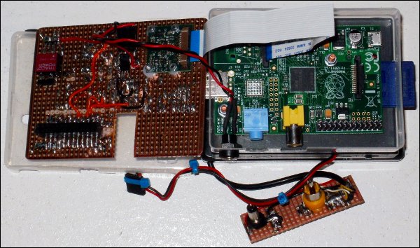
A Raspberry Pi Model A is used, as it has a much lower power requirement compared to the Model B. The Model A has a single USB port, which can be used to connect mass storage if there is a requirement to store large high definition video files.


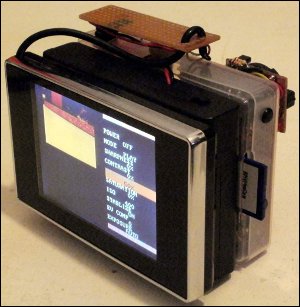
For this project I was lucky enough to get an LCD reversing monitor in a case which is already ideal for the project, and saves having to re-case it. The wires for the monitor come out of the top of the case and are soldered to a small piece of strip-board with an RCA and 2.1mm power plug which will plug directly into the Raspberry Pi and a 2.1mm power socket in the Raspberry Pi case.

The battery case is sandwiched between the Raspberry Pi case and the LCD case. The lid for the battery case is bolted to the LCD monitor case. And the battery case body is bolted to the Raspberry Pi case. This still allows access to the batteries at any time, so they may be replaced freely. A full charge of 6 AA 2400mAh NiMH batteries lasts ~6 hours with the monitor on, if the monitor is allowed to sleep a full charge should last longer.

Software
The software is very simple, all of the difficult bits are done in the Raspberry Pi Foundation's command line utilities raspivid and raspistill. The application is just a menu system which reads the menu items data from a text file and displays it on the monitor. The only other thing displayed is a preview of the image from the camera with the selected options set, using raspistill.

The user select the options they require and the raspistill utility is restarted to display the changed command line options. When the user clicks the record button, the preview is terminated and then either raspistill or raspivid is executed to achieve the required task. The users options are stored in a file on the SD card so when the Raspberry Pi is next used, the previously used options are retained.

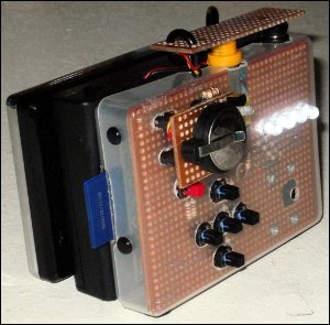
In addition the user can turn the illumination LEDs on or off, this just sets a GPIO pin high or low.

The monitor can also optionally go to sleep after a period of inactivity, this also just sets a GPIO pin high or low.

Finally the user can view a recorded video. A list of the files stored is displayed, when the user selects a video, the Raspberry Pi Foundations command line utility omxplayer is used to play the video full screen.

NOTE: Time Lapse and SD Card
I have found that a class 4 SD card is not fast enough to capture time lapse images of period 1 second, at full resolution and quality. If you experience this, reduce the quality or resolution of the image. Or increase the time lapse period.

Configuration
The software comes configured, with nothing required to do. It is possible to modify the configuration if required. The file RPiVideoCam.ini contains all of the configuration options, including the menu information.

Additional menu options can be added or existing ones altered or removed.

A menu is defined in two lines, the first MENU_?, where ? is the menu number, which has to be unique. The first entry in this line is the menu name, followed by the menu item names. The menus are displayed in order of their menu number. This first line is the text displayed in the application. This can be altered as required, it is comma separated and each entry should be at least one character long.

The second line is the MENU_VALUE_?, this contains special instructions or command line arguments which are to be used when the menu item is selected. Each entry in this line represents the equivalent entry in the first line. The first entry is the command line argument, followed by the options text for that command line argument. The special commands are used in menus 0 and 1. In the special commands you will see references like [2], this means use the option which has been selected in menu 2 as a command line argument here.


GPIO Pin Allocation
Raspberry Pi Feature
GPIO 7 LCD Monitor Sleep
GPIO 9 LED Illumination
GPIO 8 Left
GPIO 17 Right
GPIO 11 Up
GPIO 22 Down
GPIO 10 OK
GPIO 4 Start/Stop

Strip-board the same dimensions as the case, is used to place the circuit components onto. Connectors are arranged on the strip-board so that it can be plugged directly onto the Raspberry Pi GPIO connectors. The Raspberry Pi Camera board is small enough that it can be mounted to the back of the strip-board and sits recessed inside the case. This is ideal as it protects the camera. Switches, LEDs and resistors are mounted on the top of the strip-board, the transistors are mounted to the back of the strip-board.


The following files are distributed in the package:
README.txt     - Information about the package.
License.txt    - User license agreement.
License.dat    - License file.
RPiVideoCam    - Linux application.
RPiVideoCam.ini- Application configuration file.

Download
V1.00 2014-01-02 - Photo, video and time lapse.

Download the driver package here.

Install
Install Arch Linux onto an SD card, and then update the OS using the following command:
pacman -Syu

Configure the OS to automatically login after booting by typing the following commands:
cp /usr/lib/systemd/system/getty\@.service \
/etc/systemd/system/getty.target.wants/autologin\@tty1.service

Edit the file text:
/etc/systemd/system/getty.target.wants/autologin\@tty1.service

After the section in the file called [Service], add the text -a root to the following line:
ExecStart=-/sbin/agetty --noclear -a root %I 38400

After the section in the file called [Install], add the following line of text:
Alias=getty.target.wants/autologin@tty1.service

Issue the following commands at the console:
systemctl daemon-reload
systemctl disable getty@tty1
systemctl enable autologin@tty1
systemctl start getty@tty1

Edit the text file /boot/config.txt and replace it's contents with the following:
test_mode=0
disable_splash=1

start_file=start_x.elf
fixup_file=fixup_x.dat
disable_camera_led=1

framebuffer_width=320
framebuffer_height=200
overscan_left=-15
overscan_right=-15
overscan_top=-35
overscan_bottom=-35

gpu_mem_512=316
gpu_mem_256=128
cma_lwm=16
cma_hwm=32
cma_offline_start=16

Unpack the application into the directory /root/RPiVideoCam/:
cd /root/
gunzip RPiVideoCam.tar.gz
tar -xf RPiVideoCam.tar
mkdir /mnt/DISK/

Edit the file /root/.bash_profile and replace it's contents with the following:
setterm -blank 0
export PATH=$PATH:/opt/vc/bin
cd /root/RPiVideoCam/
./RPiVideoCam
shutdown -h now


Example Time Lapse Video Recording

Example Video Recording


Example Photographs (Click To Enlarge)


Project Cost
Item Reference Qty Each Cost
Stripboard 160 x 100mm, 61 holes x 35 holes HW099 BitsBox 1 £1.99 £1.99
Header Strip 0.1" Pitch Single Row 4-Way CN202 BitsBox 2 £0.08 £0.16
Crimp Housing 0.1" pitch 4-way CN118 BitsBox 2 £0.30 £0.60
Crimp sockets CN120 BitsBox 8 £0.09 £0.72
Single Row Sockets 0.1" pitch. 14-way BitsBox 2 £0.40 £0.80
470R Resistor Carbon film 1/4W 5% BitsBox 4 £0.04 £0.16
1K Resistor Carbon film 1/4W 5% BitsBox 8 £0.04 £0.32
5mm White LED BitsBox 4 £0.34 £1.36
BC337 Transistor BitsBox 2 £0.09 £0.18
Tactile switch 6x6mm - Round Button Black BitsBox 5 £0.20 £1.00
Tactile switch 6x6mm - Round Button Red BitsBox 1 £0.20 £0.20
Phono Plug BitsBox 1 £0.22 £0.22
DC Power Plug 2.1mm BitsBox 1 £0.36 £0.36
DC Panel-mount Power Socket 2.1mm BitsBox 1 £0.76 £0.76
Playing Card Case eBay 1 £1.75 £1.75
4GB SD Card eBay 1 £4.59 £4.59
6xAA Battery Holder eBay 1 £3.48 £3.48
3.5" Composite Monitor eBay 1 £17.99 £17.99
5V Regulator TSR1 2450 Farnell 1 £4.80 £4.80
Raspberry Pi Model A Farnell 1 £20.06 £20.06
Raspberry Pi Camera Farnell 1 £19.88 £19.88
TOTAL £81.38

Loading...