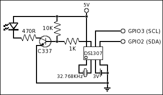
www.NewsDownload.co.uk Page 25

Raspberry Pi Battery Backed Real Time Clock

2013-12-07 21:22 By Jason Birch

Very low power clock module which maintains the system time and date on the Raspberry Pi while it is powered off. Run from a single button cell to last up to ten years.

VIDEO
The video here demonstrates the project which this article describes how to build.

The article breaks the project down into several stages:

  • Circuit
  • Build
  • Software
  • Project Costing

Reference:


Circuit for RTC Module

Circuit
Though the DS1307 operates from a supply voltage of 5V, the I2C pins which connect to the Raspberry Pi GPIO are "open drain", which means the IC will sink current and not supply current. The Raspberry Pi has internal pull up resistors on these pins which pull the logic up to 3V3. This means the Raspberry Pi can communicate with the IC and not be damaged by the 5V supply to the IC.

When in operation the DS1307 can output an oscillating signal on pin 7. This signal does not have to be used, but I have connected a transistor to it so an LED can flash once a second. This part of the circuit is optional and will have no effect on the operation of the device if it is not implemented. So to save money, the resistors, LED and transistor can be omitted if desired.


The crystal runs at 32.768KHz. If repeatedly divided by two this can be reduced to a 1Hz clock, one cycle per second, which is why this frequency is used. When computers move the bits of a number one position to the right, this divides the number by two. For example 52 decimal is 110100. Shifting the bits one to the right gives 11010 which is 26 decimal, half of 52.

Use this principle on 32768Hz. 32768 / 2 = 16384 / 2 = 8192 / 2 = 4096 / 2 = 2048 / 2 = 1024 / 2 = 512 / 2 = 256 / 2 = 128 / 2 = 64 / 2 = 32 / 2 = 16 / 2 = 8 / 2 = 4 / 2 = 2 / 2 = 1. Thus providing a signal which occurs exactly once every second, which can be used to count the seconds in a date and time.

According to the data sheet for the DS1307 a single coin cell can last up to ten years. Which will maintain the date and time from the coin cell alone, when there is no 5V supply present.

The use of the device itself is very simple. All that is required is a 3V supply to maintain the date and time with a 32.768KHz crystal. When the date and time is to be written to or read from the device, a 5V supply is required and the data is transferred via the I2C standard over only two GPIO pins.

Build
The circuit is placed on a small piece of strip board and arranged so that it can be plugged into the leftmost six pins of the Raspberry Pi GPIO header. Care must be taken to plug the board into the correct pins on the GPIO header as there are no polarizing guides on the GPIO header. My connectors are slightly wider apart as they plug into an additional intermediate board.

The crystal should be placed as close to the IC as possible because it is powered with very little current and can be prone to high frequency interference from other electrical devices.

Software
The software is a command line application which communicates with the device and either sets the date and time on the device, or on the system.

Communication over the I2C pins on the Raspberry Pi rely on the system clock running at it's default value. So ensure that this value has not been changed in the /boot/config.txt file.

Initially the device has no date and time set. The first thing to do, and also after replacing a battery is to manually set the system time and tell the device to set itself from the system time. Do this with the following commands. Replace yyyy-mm-dd hh:mm:ss with the current date and time:
date -s 'yyyy-mm-dd hh:mm:ss'
/root/RPiRTCDriver/RPiRTC /I

Now check the date and time on the device by running the following command. It will display three dates and times. The first is the last time the date and time of the system was set from the device. The second is the date and time on the device. And the third is the date and time on the system:
/root/RPiRTCDriver/RPiRTC /G

To set the date and time of the system from the device, use the following command. This needs to be done automatically when the system boots, see the install instructions to the right.
/root/RPiRTCDriver/RPiRTC /S

The device also has some memory which can be used to store other data. The software has an option to store a message in this memory, for example using the following command. To view the message use the command with the /G option, and the message is displayed as the first line:
/root/RPiRTCDriver/RPiRTC /M 'Test message'


GPIO Pin Allocation
Raspberry Pi DS1307
5V Vcc (Pin 8)
I2C1 SDA (GPIO 2) SDA (Pin 5)
I2C1 SCL (GPIO 3) SCL (Pin 6)
GND GND (Pin 4)


The following files are distributed in the package:
README.txt    - Information about the package.
License.txt   - User license agreement.
License.dat   - License file.
RPiRTC        - Linux driver application.
RPiRTC.ini    - Driver configuration file.

Download
V1.00 2013-12-07 - Initialize, set system time
                          and custom message.
V1.01 2017-03-31 - Raspberry Pi 2/3 compatibility.

Tested
 Raspberry Pi (Original)
 Raspberry Pi 2
 Raspberry Pi 3
 Raspberry Pi Zero

Download the driver package here.

Install
For Linux distributions...
Copy the driver files into the directory:
/root/RPiRTCDriver/

The software only has to run once when the system is booting. This can be done as a cron job. To do this, at the command line type:
crontab -e

The system text editor will be used to edit the list of cron jobs. Add the following line and then save the file:
@reboot /root/RPiRTCDriver/RPiRTC /S


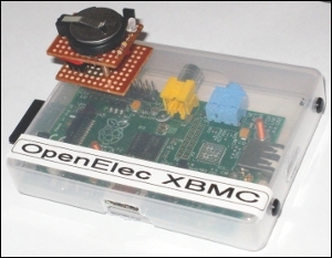
When using with OpenElec XBMC...
Copy the driver files into the directory:
/storage/downloads/RPiRTCDriver/

The software only has to run once when the system is booting. To do this, edit the file:
/storage/.config/autostart.sh
Add the following line and then save the file:
/storage/downloads/RPiRTCDriver/RPiRTC /S

OpenElec XBMC at the time of writing sets the date and time minus one hour for some reason, which does't occur on Arch Linux or Raspbian. So when using OpenElec XBMC, set the time on the device plus one hour to work around this.


Project Cost
Item Reference Qty Each Cost
Cell holder - PCB mount for 20mm coin cells BitsBox 1 £0.59 £0.59
CR2032 Battery Poundland 1 £1.00 £1.00
Stripboard 25 x 64mm 9 holes x 25 holes BitsBox 1 £0.31 £0.31
Single Row Sockets 0.1" pitch 3 way BitsBox 2 £0.23 £0.46
470R Resistor Carbon film 1/4W 5% BitsBox 1 £0.04 £0.04
1K Resistor Carbon film 1/4W 5% BitsBox 1 £0.04 £0.04
10K Resistor Carbon film 1/4W 5% BitsBox 1 £0.04 £0.04
3mm Green LED BitsBox 1 £0.10 £0.10
BC337 Transistor BitsBox 1 £0.09 £0.09
32.768KHz Crystal BitsBox 1 £0.30 £0.30
DS1307 Real Time Clock BitsBox 1 £3.59 £3.59
8-pin DIL socket BitsBox 1 £0.12 £0.12
TOTAL £6.68

Loading...