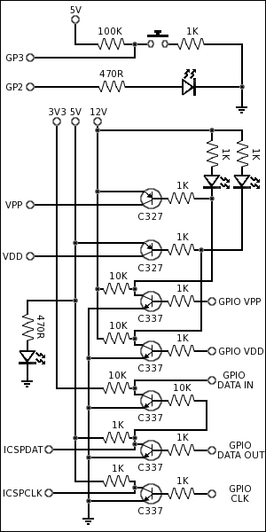
A PIC device requires two communication lines. A clock line to synchronize communication. This is just level shifted with a transistor from 3V3 of the Raspberry Pi to 5V of the PIC device. The NPN transistor incidentally inverts the signal, this is then taken into account in the Python application by using a constant to reference the GPIO line value. The other communication line is the data line. This is more complex as it is bi-directional. The Raspberry Pi GPIO lines are not bi-directional. So a transistor is used to level shift Raspberry Pi communications to 5V and another transistor is used to level shift PIC communication to 3V3. This also has the effect that anything the Raspberry Pi writes to the PIC write GPIO pin, can also be read on the Raspberry Pi in GPIO pin. This effect is used to detect if the programmer hardware is present by the Python application.
EXAMPLES
In the sub directory of the software, TEST_ASM, there are device specific assembly test programs, which can be cross compiled and programmed to a physical device with the programmer. These test programs use the button and LED test circuit and will flash the LED three times when the button is pressed. These can be used to prove the programmer is working correctly with the specific device in use.
CONFIGURATION
There are only a couple of things which require configuration. The first is the boost converter needs to be set to 12V75 before a device is plugged into the hardware. These boost converters can boot the voltage to 30V and higher, so it is a good idea to set the device voltage with a volt meter before adding it to the project. I place a small amount of thread lock to the side of the screw head after setting to hold the setting in place.
On some PIC devices there is a pin named PGM, this should be tied to 0V with a high value resistor during programming. The pin can be used to select high or low voltage programming, to erase a device high voltage programming is required. So the software is written to support high voltage programming only.
The only other thing which needs to be set is the GPIO pin allocation you have used in the application. These values are set at the top of the PIC.py file.
PIC PROGRAMMER OPERATION
The PIC Programmer application can perform the following operations:
./RPiPIC.py -P
Power on current device.

./RPiPIC.py -O
Power off current device.

./RPiPIC.py -L
List currently supported PIC devices.

./RPiPIC.py -C [PIC_DEVICE]
Display device memory checksum.

./RPiPIC.py -D [PIC_DEVICE]
Read memory from device and display.

./RPiPIC.py -B [PIC_DEVICE]
Blank check device.

./RPiPIC.py -E [PIC_DEVICE]
Erase all device memory.

./RPiPIC.py -R [PIC_DEVICE] [FILE_NAME]
Read memory from device and save to .hex file.

./RPiPIC.py -W [PIC_DEVICE] [FILE_NAME]
Read .hex file and write to device memory.

./RPiPIC.py -V [PIC_DEVICE] [FILE_NAME]
Read memory from device and read .hex file,
then verify data.

./RPiPIC.py -LM [PIC_DEVICE]
List device memory areas.

./RPiPIC.py -LD [PIC_DEVICE] [MEMORY_AREA] [DATA]
Load data into a device memory area.
LINUX PIC CROSS COMPILER TOOLS
Run the following installs as root user to install packages for PIC Microchip development, such as a cross compiler, linker and debugging tools:
apt-get install gpsim
apt-get install gputils
apt-get install sdcc
Tools installed from the Linux Packages above:
Cross compile a PIC Microchip assembly text file.
gpasm -w 1 -c [FILE_NAME].asm
Link a PIC Microchip object file and produce a Intel HEX formatted object file.
gplink -o [FILE_NAME].hex [FILE_NAME].o
Simulate a compiled PIC Microchip code file for debugging.
gpsim -s [FILE_NAME].cod
PIC Microchip disassembler.
gpdasm
Discard symbols from a PIC Microchip object file.
gpstrip
PIC Microchip object file viewer.
gpvo
PIC Microchip cod file viewer.
gpvc
PIC Microchip object library manager.
gplib
|
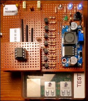
HARDWARE
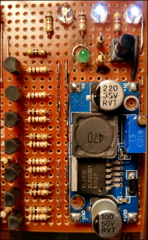
The hardware is remarkably simple. A boost converter module is used to boost the Raspberry Pi 5V supply to 12V75, which is required to program a Microchip PIC micro-controller. This means an additional power supply is not required. These boost converter modules are available for around £2.50, which is far less then the component parts would cost to build one. It doesn't need to be very powerful, the PIC guide says it only has to supply up to 100mA.
The remainder of the circuit is a few transistors, resistors, LEDs and a switch. A very cheap project to put together and will provide a platform for many interesting projects using micro-controllers.
The transistors perform a couple of tasks, switching on power and data level shifting in two directions.
A Microchip PIC device requires ~12V75 for programming a device, but must be switched on at a specific time. To do this an NPN transistor is first triggered by the Raspberry Pi on a GPIO line. The output of this transistor is pulled up to 12V75, so when switched off the output is 12V75. When switched on the transistor pulls the output to 0V. This will illuminate an LED which is held at 12V75 on its opposite side. It also switches on a PNP transistor, which supplies 12V75 to the PIC device. The PIC device also requires a 5V supply, which also needs to be switched on at a specific time. This is provided in the same way as the 12V75 supply, but with a different Raspberry Pi GPIO line.
Finally there is a test circuit, for a PIC test application, which allows the programming process to be physically proven when testing the programmer hardware. It is a switch connected to an input IO pin on the PIC device. And an LED connected to an output IO pin on the PIC device, to visibly show the PIC program running on the PIC device when the switch has been pressed.
SOFTWARE
The software is written in Python and is available here: Python PIC Programmer
The install of the Python code is just to checkout the latest version of the code from GitHub and run from the directory it is checked out into.
Tested
 Raspberry Pi (Original) Raspberry Pi (Original)
 Raspberry Pi 2
Raspberry Pi 3
Raspberry Pi Zero Raspberry Pi 2
Raspberry Pi 3
Raspberry Pi Zero
├── GNU-GeneralPublicLicense.txt
├── RPiPIC.py
│   PIC Microchip programmer application.
├── PIC_API.py
│   API level PIC Microchip device control.
├── PIC.py
│   Low level PIC Microchip device control.
├── HEX_File.py
│   Intel HEX file format handler.
├── PIC_DEVICES.py
│   Definitions of PIC Microchip devices.
├── README.txt
│   Information about the project.
└── TEST_ASM
    Example code for supported PIC devices.
    ├── INCLUDE
    │   PIC Microchip device asm include files.
    │   ├── P12F675.INC
    │   └── P12F683.INC
    ├── PIC12F675
    │   Example code for a PIC Microchip PIC12F675
    │   ├── Build.sh
    │   ├── PIC12F675.asm
    └── PIC12F683
        Example code for a PIC Microchip PIC12F683
        ├── Build.sh
        ├── PIC12F683.asm
ADDING PIC DEVICE SUPPORT
It has been written to allow additional PIC devices to be added by adding additional data definitions in the PIC_DEVICES.py file. They are defined by listing and defining the memory locations which are in the specific device. The device must use the Microchip PIC serial interface to be programmed with this hardware and software.
There are some PIC devices which will not be able to be defined in this application; Older PIC devices use EPROM and ROM, these devices use UV light to be erased and are not programmed using the Microchip PIC serial interface. There are also some devices which have a memory type which requires the memory location to be pulsed with 100uS pulses. It is possible to achieve this pulse width in Python, just, but Python is not accurate enough to keep the pulse width consistent and reliably below 100uS. So devices of this type can not be programmed with this hardware or software, unless an OS level workaround is used with a low level programming language.
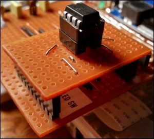
Of the data sheets for the PIC micro-controllers I have looked at, the pins for serial programming look like they are typically all in the same location in the top eight pins of the device. This should mean that most devices should be able to use the same socket to be programmed, as long as the device is positioned at the top of the socket, and the spec is checked to verify the pins are located at the same top eight pins. However, I have made a device board, which plugs into the programmer, with the following lines being provided to the board, which will allow a custom layout for any devices not complying to the layout: 12V 5V 3V3 0V VDD VPP DATA CLK LED Switch
|