Hardware
The hardware has several elements, all of which are simple to understand. There is a pair of transistors so that the LCD can be powered off using software to improve battery performance. There are a pair of transistors to change the voltage levels on the RS232 Tx and Rx lines. There is a switched mode 5V regulator to provide power for the Raspberry Pi from the battery pack. There is an 20 x 4 character LCD display and four LEDs to display information to the user and four switches to receive information from the user.
|
First Blue LED
|
GPIO 2
|
|
Second Blue LED
|
GPIO 25
|
|
Red LED
|
GPIO 3
|
|
Yellow LED
|
GPIO 27
|
|
Green LED
|
GPIO 23
|
|
Switch 1
|
GPIO 4
|
|
Switch 2
|
GPIO 17
|
|
Switch 3
|
GPIO 22
|
|
Switch 4
|
GPIO 24
|
|
LCD 0V Power Off
|
GPIO 30
|
|
LCD 5V Power Off
|
GPIO 31
|
|
LCD Enable Control Line
|
GPIO 7
|
|
LCD Register Select Control Line
|
GPIO 8
|
|
LCD Data bit 4 Line
|
GPIO 11
|
|
LCD Data bit 5 Line
|
GPIO 9
|
|
LCD Data bit 6 Line
|
GPIO 10
|
|
LCD Data bit 7 Line
|
GPIO 18
|
|
RS232 Tx
|
GPIO 14
|
|
RS232 Rx
|
GPIO 15
|
20 x 4 Character LCD Module
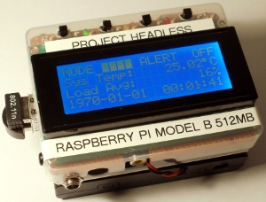
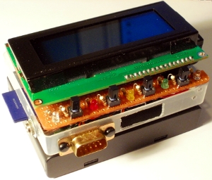
The module fits really neatly into the playing card case I use for my projects. The module comes with out a header installed, so a 16 pin right angle header was used in order to keep the profile of the device as low as possible. A right angle header was also added to the stripboard which mounts directly on the Raspberry Pi header pins. To connect the two headers together a couple of 16 pin header connectors where wired together with short wires. The header connectors needed to be trimmed a bit as space was tight.
The LCD module has a 5V power supply which goes to the logic, back light and LCD. The LCD supply is generated using a 10K variable potential divider between 5V and 0V, this effectively creates an adjustable contrast control. The power is switched on and off using two GPIO pins which switch a couple of transistors. A PNP transistor is required to switch the positive side and an NPN transistor is required to switch the negative side. To power the LCD module, the PNP needs to be held low and the NPN needs to be held high. To switch off the LCD module I make the GPIO pins high impedance as inputs. Each time the module is powered up in software, it is important to remember to run the re-initialize routine again and display the last displayed text again.
The LCD module has control lines which need to be driven from GPIO pins. It has a read and write mode.
IMPORTANT: The LCD module must never be in read mode because it will output 5V signals to the GPIO pins, which will damage the GPIO circuity in the Raspberry Pi. To prevent this the R/!W pin is connected directly to 0V so the device is permanently in write mode.
There are eight data pins, luckily the module can be used in 4 bit mode, which means only the upper four data lines (D4 - D7) need to be connected to GPIO pins. This is done via 1K resistors as a precaution. A data line called Register Select is connected via a 1K resistor to a GPIO line, this selects if the data being sent is a command or character data. Finally there is a data line called Enable which is also connected to a GPIO pin via a 1K resistor, this tells the module when there is some data to be read.
NOTE: Resistors Are Cheap
When ever I have logic data which I want to drive from a GPIO pin on the Raspberry Pi, I place a 1K resistor in line. I do this in case I make a wiring error and accidentally try and sink or source too much current from the GPIO pin. This wont protect the GPIO pin in all circumstances, but will in some and potentially give you enough time to spot the error and correct it in others. In the observation above, as the display runs off of 5V, I do not know what the effect of experimenting with switching the modules power on and off if I did not have a 1K resistor in the GPIO lines. It may have been OK, but I feel better for them being present and it's not a big expense.
LED and Switches
The LEDs and Switches are implemented in the most basic form. For LEDs there is a 470R resistor in line with a GPIO pin and the anode of the LED up to 3V3. The switches have a 1K resistor in series to a GPIO pin and the other side of the switch is taken to 0V. The GPIO is programmed to have an internal pull up resistor, reducing the amount of external hardware required.
Power supply
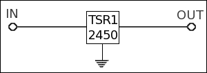
The 5V power for the Raspberry Pi is supplied from a switch mode regulator, though more expensive than a 7805, it provides much longer battery life. It is pin compatible with a 7805 regulator, so a 7805 can be substituted if required.
 System Application Software
Download
V1.00 2013-02-13 - Headless Pi application.
Download the application package here.
The application for the project consists of the following files:
README.txt            - Information about the package.
License.txt           - User license agreement.
License.dat           - License file.
HeadlessPi            - Linux application.
HeadlessPi.ini        - Application configuration file.
ArchInstall.sh        - Install script.
uninstall.sh          - Uninstall script.
HeadlessPi.service    - Install script.
RestartNetwork.sh     - Script to start network.
Place the application package into the
/root/ directory. Then run the following commands at the terminal as root:
cd /root/
gunzip HeadlessPiDriver.tar.gz
tar -xf HeadlessPiDriver.tar
cd /root/HeadlessPiDriver/
chmod +x ArchInstall.sh
./ArchInstall.sh
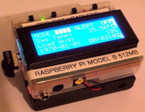
The application has a configuration file
HeadlessPi.ini. In this file the GPIO pins can be allocated to each function manually. This article describes the default settings for GPIO allocation.
Two network devices can be defined for displaying the IP address of. Also two partitions can be defined for displaying the free space of:
IP_1_NAME=eth0
IP_2_NAME=wlan0
DISK_PATH_1=/boot
DISK_PATH_2=/
Finally the levels for each of the status values can be defined for temperature, load average, free memory and swap space. DEFCON_1_* is the yellow LED, DEFCON_2_ is the red LED, DEFCON_3_ is strobe the red and blue LEDs and DEFCON_4_TEMP is to shut the system down at this level:
DEFCON_1_SYS_TEMP=50
DEFCON_2_SYS_TEMP=60
DEFCON_3_SYS_TEMP=70
DEFCON_4_SYS_TEMP=80

DEFCON_1_LOAD_AVG=100
DEFCON_2_LOAD_AVG=200
DEFCON_3_LOAD_AVG=400

DEFCON_1_FREE_MEM=100000
DEFCON_2_FREE_MEM=50000
DEFCON_3_FREE_MEM=1000

DEFCON_1_SWAP_USED=0
DEFCON_2_SWAP_USED=100000
DEFCON_3_SWAP_USED=200000