www.NewsDownload.co.uk Page 15

Raspberry Pi & XBox ChatPad

2012-12-19 14:50 By Jason Birch

Connecting a Microsoft XBox ChatPad to a Raspberry Pi is easy, the only components required are two 1K resistors. With the Freeware driver, the ChatPad can be used in Linux.

VIDEO
The video here demonstrates the project which this article describes how to build.

The article breaks the project down into several stages:

  • Hardware
  • Freeware Driver
  • Project Costing
  • Revision 2012-12-24 Keypad Mode Indicators Added

Reference:

Hardware
The requirement for the hardware is to connect the XBox ChatPad directly to the Raspberry Pi GPIO, inserting only two resistors in the TX and RX lines as a precaution. This involves the following connections:

GPIO Pin Allocation
Raspberry Pi XBox
3V3 3V3
TX (GPIO 14) RX (via 1K)
RX (GPIO 15) TX (via 1K)
GND GND

Circuit for GPIO pins to ChatPad

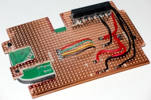
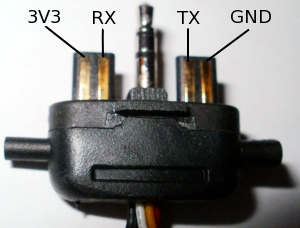
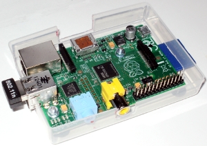
The hardware couldn't be simpler. The power for the ChatPad comes directly from the Raspberry Pi GPIO, the power consumption is very low.

The communication between the two is a standard RS232 (UART) at 19200 baud.

The Raspberry Pi uses an internal clock to generate the baud rate, it is possible to change this clock speed in the /boot/config.txt file. For this reason, it is essential that this setting remains at it's default for communication to be possible.

Either omit the core_freq=250 or ensue it is set to 250 in the /boot/config.txt file.

There is a 1K resistor on each data line to restrict the current flowing from the GPIO pins, in case either pin has been configured to an alternate operation.


The board is cut to fit around the tall components on the Raspberry Pi board, to keep the profile of the overall case as low as possible.

The headers are just the right height to mount the board on the Raspberry Pi.

The circuit is very simple, just four wires coming from the ChatPad and soldered to the strip board. Two wires then go directly to the 3V3 power supply on the GPIO header. The other two wires go to the GPIO header via two 1K resistors.
The strip board mounts directory on the header pins which hold the board in place. The direction I have located the ChatPad means the composite video port is at the top. So a PAL LCD display and audio amp can be mounted on top of the composite and audio sockets.
The boards communicate with each via UART (RS232) devices, which communicate at 19200 baud, 1 stop bit, 1 start bit, 8 bit data, no parity, no handshake.

The ChatPad needs to be initialized before it will start sending key press data, send [ 0x87, 0x02, 0x8C, 0x1F, 0xCC ] to initialize. Then it needs to be kept awake every second, or it will stop sending key press information, send [ 0x87, 0x02, 0x8C, 0x1B, 0xD0 ] to keep awake. When it does send the key press information, it always sends duplicate data. I am guessing this is because there is no handshaking, in case some data is lost.
The ChatPad pin out is shown here. Always double check the power pins and polarity and always beep through each pin to the ChatPad PCB. With various versions and manufactures of the device, the pin-out on the PCB may change over time.

I found the copy of the Broadcom Data-sheet I had has many typos. One of the main ones is to set the Mini UART into 8 bit mode, set bit 0 of the register, I found bit 0 and bit 1 needed to be set.

The Raspberry Pi is mounted in the lower part of the case using the mounting holes on the Rev 2 Raspberry Pi.

With the ChatPad in place the console is a very compact device with lots of potential for future projects.

Freeware Driver & Configuring the Driver
I have updated my Raspberry Pi Remote Keypad Driver to support the XBox ChatPad.

The driver can be downloaded and full details for configuration, can be found in this article:

Raspberry Pi GPIO Keypad Driver

Project Cost
Item Reference Qty Each Cost
1K Resistor Carbon film 1/4W 5% BitsBox 2 £0.04 £0.08
Kynar Wire - 5m length BitsBox 1 £1.55 £1.55
Single Row Sockets 0.1" pitch (14-way) BitsBox 2 £0.40 £0.80
Stripboard 127 x 95mm 50 holes x 36 holes BitsBox 1 £1.59 £1.59
Pozi Pan Head Machine Screws M2.5 10mm BitsBox 2 £0.03 £0.06
Nuts M2.5 BitsBox 2 £0.02 £0.04
Washers M3 BitsBox 4 £0.025 £0.10
BitsBox Shipping BitsBox 1 £1.75 £1.75
Playing Card Case eBay 1 £0.99 £0.99
XBox ChatPad eBay 1 £11.48 £11.48
SUB TOTAL £18.44
Raspberry Pi Farnell (element 14) 1 £33.16 £33.16
TOTAL £51.60

UPDATE 2012-12-24
Keypad Driver V1.02 is now more stable and support for keypad mode indicators has been added.

An entry in the configuration file MODE_INDICATOR_GPIO_PINS lists the GPIO pins which are used to indicate the currently locked key mode for the keypad. Replace entries with -1 to free up the GPIO pin for other uses.

Key mode indicators are allocated to GPIO pins 22, 23, 24 and 25 by default. An LED can be added to the GPIO pin via a 470R resistor to visibly show when the Shift, Circle, Square or MSN mode is locked.

The LED anode is then held high so that the GPIO pin sinks current.
Additional Cost
Item Reference Qty Each Cost
470R Resistor Carbon film 1/4W 5% BitsBox 4 £0.04 £0.16
3mm Red LED BitsBox 1 £0.09 £0.09
3mm Yellow LED BitsBox 1 £0.10 £0.10
3mm Green LED BitsBox 1 £0.10 £0.10
3mm Amber LED BitsBox 1 £0.10 £0.10
TOTAL £0.55

Loading...