www.NewsDownload.co.uk Page 20

Raspberry Pi & PSP Analog Joystick

2013-04-02 10:12 By Jason Birch

Connecting a PSP analog thumb joystick to a Raspberry Pi is easy, the only components required are a 1K resistor and an MCP3002 analog to digital converter. With the Freeware driver, the joystick can be used in Linux.

VIDEO
The video here demonstrates the project which this article describes how to build.

The article breaks the project down into several stages:

  • Hardware
  • Freeware Driver
  • Project Costing

Reference:

Hardware
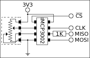
The requirement for the hardware is to connect the PSP Analog Joystick to the Raspberry Pi GPIO via an MCP3002 Analog to Digital Converter, inserting only one resistor in the MCP3002 data output line as a precaution.

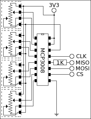
Support has now been added for up to four joysticks using and MCP3008 in place of the MCP3002.

This involves the following connections:

Single Joystick Using An MCP3002
GPIO Pin Allocation
Raspberry Pi MCP3002
3V3 VDD / Vref (Pin 8)
SPI0 CE1 (GPIO 7) N/C
SPI0 CE0 (GPIO 8) CS (Pin 1)
SPI0 MISO (GPIO 9) Dout (Pin 6)
SPI0 MOSI (GPIO 10) Din (Pin 5)
SPI0 SCLK (GPIO 11) CLK (Pin 7)
GND VSS (Pin 4)
PSP Joystick MCP3002
3V3 VDD / Vref (Pin 8)
X Axis CH0 (Pin 2)
Y Axis CH1 (Pin 3)
GND VSS (Pin 4)

Circuit for GPIO pins to MCP3002

The hardware is very simple. The power for the MCP3002 and joystick comes directly from the Raspberry Pi GPIO, the power consumption is very low.

The communication between the two is a standard SPI.

There is a 1K resistor on the data out line of the MCP3002 to restrict the current flowing from the GPIO pins, in case the GPIO pin has been configured to an alternate operation.

The PSP joystick has four pads on the back were wires can be soldered on to. Two of the pads require the 3V3 supply across them, the pads at each end, 1 and 4. The joystick is the equivalent of a variable resistor, but with two wipers, one for each axis movement. So the way it works is that it creates two potential dividers which provide a varying voltage for each axis, x and y. The inner pads 2 and 3 are the X and Y axis.


Four Joysticks Using An MCP3008
GPIO Pin Allocation
Raspberry Pi MCP3008
3V3 VDD
3V3 Vref (Pin 15)
SPI0 CE1 (GPIO 7) N/C
SPI0 CE0 (GPIO 8) CS (Pin 10)
SPI0 MISO (GPIO 9) Dout (Pin 12)
SPI0 MOSI (GPIO 10) Din (Pin 11)
SPI0 SCLK (GPIO 11) CLK (Pin 13)
GND DGND (Pin 9)
PSP Joystick MCP3008
Joystick 1 - 3V3 VDD / Vref (Pin 8)
Joystick 1 - X Axis CH0 (Pin 1)
Joystick 1 - Y Axis CH1 (Pin 2)
Joystick 1 - GND AGND (Pin 14)
Joystick 2 - 3V3 VDD / Vref (Pin 8)
Joystick 2 - X Axis CH2 (Pin 3)
Joystick 2 - Y Axis CH3 (Pin 4)
Joystick 2 - GND AGND (Pin 14)
Joystick 3 - 3V3 VDD / Vref (Pin 8)
Joystick 3 - X Axis CH4 (Pin 5)
Joystick 3 - Y Axis CH5 (Pin 6)
Joystick 3 - GND AGND (Pin 14)
Joystick 4 - 3V3 VDD / Vref (Pin 8)
Joystick 4 - X Axis CH6 (Pin 7)
Joystick 4 - Y Axis CH7 (Pin 8)
Joystick 4 - GND AGND (Pin 14)

Circuit for GPIO pins to MCP3008

The MCP3002 analog to digital converter has two channels, which is handy, one for each axis. The supply voltage for the MCP3002 is also referred to as the reference voltage, so the output from the two potential dividers in the joystick connect directly to the channel inputs of the MCP3002.

The MCP3002 can be powered by 3V3, so it can connect directly to the Raspberry Pi GPIO pins without the need for any interfacing electronics. It communicates using SPI, which means it just connects directly to the GPIO SPI pins. I have however placed a 1K resistor in the Dout line of the MCP3002 in case the Raspberry Pi line becomes an output at any time, this is to prevent too much current being drawn from either device if this were to ever occur.
Communication with the MCP3002 is very simple, it only requires five bits of data to be sent to it. The first bit sent is ignored, the second bit is 1 to indicate the start of communication. Then a bit for mode of operation 1 to allow both channels to be used independently. Followed by a channel select bit and the final bit is 0. The SPI protocol receives a bit of information each time one is sent. The bits received while sending these five bits are ignored. In order to receive the digital value back from the device a further 11 bits of data need to be sent, these bits are arbitrary so just send bit value 0. Of the sixteen bits sent to the device sixteen bits will be received back, only the last 10 bits contain data, which is the digital value of the channel requested. To receive the value of channel 0 I send the data 0x60, and to receive the value of channel 1 I send the data 0x70.

Freeware Driver & Configuring the Driver
I have updated my Raspberry Pi Remote Keypad Driver to support the PSP Joystick.

The driver can be downloaded and full details for configuration, can be found in this article:

Raspberry Pi GPIO Keypad Driver
On the Raspberry Pi there are two CS lines, I only use one here to select the MCP3002 device. The other one can be used to connect an additional SPI device, maybe another MCP3002 would give two more axis which could be used for throttle and break in a future release of the driver at some time.

Project Cost
NOTE: Because of the small number of items for this project, cost savings can be made if the components are part of a bigger order, from better suppliers.
Item Reference Qty Each Cost
1K Resistor Carbon film 1/4W 5% eBay 1 £1.00 £1.00
MCP3002 Analog To Digital Converter eBay 1 £3.20 £3.20
PSP Thumb Analog Joystick eBay 1 £1.89 £1.89
TOTAL £6.09

Loading...