The principles of the Joule Thief circuit. A circuit to increase the voltage of a power source to a higher voltage in order to drive a load depending on a higher voltage to work.
VIDEO
Showing the basic Joule Thief circuit in operation, pointing out waveforms, voltages and current draw.
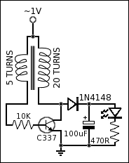
Circuit for Joule Thief
The circuit is based around an inductor oscillating a current through a switching transistor. When a current flows through the windings of an inductor, it generates a back EMF (electro magnetic field). Based on the number of turns in the inductor, this creates a reverse voltage which is higher than the forward voltage.
The inductor in this circuit has two windings. The first which goes to the base of the NPN transistor via a 10K resistor, the DC forward voltage switches on the transistor and allows the voltage to flow through the second winding which has more turns. This current through the second winding disrupts the current in the first winding as the windings are wound in opposing directions, the magnetic flux over powers the first winding, which has fewer turns and so switches the transistor off. However a much larger current flowed through the second winding and this has generated a relatively large voltage, which is momentarily stored in the inductor coil.
The voltage stored in the second winding, with the transistor switched off, passes through the rectifying diode and is stored in the smoothing capacitor as at this time it is the path of least resistance. This means the voltage in the second winding has been dissipated and no longer opposes any voltage in the first winding, so the transistor is free to switch on again and repeat the process.
When the smoothing capacitor is full, it no longer conducts, this point is now held at DC voltage. The path of least resistance is now the LED and 470R resistor (this resistor value can be much lower, depending on how high the DC voltage being generated is). The LED now lights up.
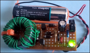
Joule Thief Boost Converter
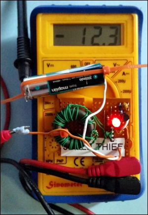
Joule Thief Consuming 12mA
Joule Thief Boost Converter
Joule Thief Boost Converter
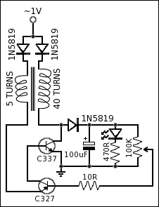
Some additional modifications have been made to the original circuit in order to make the circuit more efficient. The goal was to be able to switch off the boost converter for periods when the smoothing capacitor is charged.
A germanium diode was added between power and each winding to prevent noise at the power supply. The 20 turn winding was increased to 40 turns in order to increase the strength of the magnetic flux. The signal diode was changed to a germanium diode to reduce inefficiencies. And the main change was to introduce a second transistor with variable resistor, as a potential divider, in order to switch off the converter when the smoothing capacitor reaches the required charge.
POWER CONSUMPTION RESULTS
IDLE
5.1mA x 1.28V = 6.5mW
2 LED
7.7mA x 3.75V = 28.9mW
26.2mA x 1.28V = 33.5mW
Efficiency
28.9mW / 33.5mW x 100 = 86.2%
1 LED
5.6mA x 4.61V = 25.8mW
21.1mA x 1.28V = 27.0mW